


- Changchun Rongde Optics
- Co.,Ltd.
- Add:No.1666 Yaan Road,
- North Lake Development District,
- Changchun 130102,China
- Tel:86-431-81881745
- Fax:86-0431-85256892
- E-mail:rongdecui@roundss.net
- Skype:adacui_roundss
Company News
Current position :Home > News > Photoelectric Sense
Encoder, resolver interface method and application characteristics!
Changchun Rongde Optics Co.,Ltd. Release time:2016/7/12 Browse:1025Encoder, resolver interface method and application characteristics
Encoder development history
Early encoder main resolver, resolver IP value is high, some of the more able to work under harsh environmental conditions, because although sensitive to electromagnetic interference and other shortcomings of the decoding complexity gradually withdraw, but to date, still has its unique value, such as hybrid cars speed feedback, almost irreplaceable, in addition to the harsh environment of the steel industry, water conservancy and hydropower industry, the rotary transformer because of its high degree of protection the same access to a wide range of applications. With the development of semiconductor technology, then there will be a Hall sensor and optical encoder, Hall sensor accuracy is not high but the price is cheap, but not high temperature, suitable for use only in case of some low-end, optical encoder is due to overcome the first two disadvantages arising from the encoder, it is high precision, strong anti-jamming capability, the interface is simple and easy to use so that access to the most widely used. Encoder manufacturers many here to Tamagawa products as an example. The following resolver, incremental encoder, absolute encoder as an example introduced one by one.
Resolver
Resolver signal component is referred to as An output voltage with the rotor angle change. When the field winding to a certain frequency AC excitation voltage, output voltage amplitude of the rotor winding angle to the sine and cosine function, or to maintain a certain ratio relationship, or within a certain angle range is linear and angular.
Divided by excitation mode, Tamagawa rotary transformer and BRX two kinds of BRT, BRT is a single-phase excitation two-phase output; BRX is the phase excitation single-phase output. Users often choose resolver BRT type, because it is easy to decode.
Resolver decoded
Figure 4 Resolver electrical schematic.
Rotary specific function change between the input and output voltage is as follows:
The rotation of the rotor angle θ, the primary coil voltage (i.e. excitation voltage): ER1-R2 = E * Sin2πftf: excitation frequency, E: signal amplitude
Then the output voltage ES1-S3 = K * E * Sin2πft * Cosθ; ES2-S4 = K * E * Sin2πft * SinθK: transmission ratio, θ: the angle of the rotor deviation from the origin
So that θ = ωt, ie rotor do uniform motion, then the function curve of the output signal can be expressed as shown in FIG. 5,
FIG signal frequency f, that is, the excitation signal frequency, maximum amplitude E, the envelope signal is Sinωt and Cosωt, resolver decoder is to obtain location information by detecting these two sets of output signals.
Not difficult to see, the higher the excitation frequency, the higher the precision resolver decoding, while the amplitude of the excitation voltage is no obvious effect on the decoding. Only up to a certain voltage value can, in general, 3V ~ 1.2 times the rated voltage can meet the needs decoding.
Tamagawa Resolver for their development of a dedicated decoder chip AU6802N1, decoding board supports 10KHZ excitation frequency, the transmission ratio of 0.5, can provide incremental and absolute output signal while incremental output 1024C / T, using the long-term output; absolute output 12 / T, output using optical isolation, may need to be adjusted according to the customer when necessary. Converted signal and encoder is no different.
When using resolver decoder board ships should pay attention to three parameters: the transmission ratio, excitation voltage, excitation frequency. Transmission ratio is the ratio of the output voltage and the input voltage, the excitation voltage is the input voltage across the primary winding of the rotary transformer on the Tama River, the excitation voltage can allow rated voltages from 3V to 1.2 times. These three parameters need to exactly match to normal decoding.
Figure 5
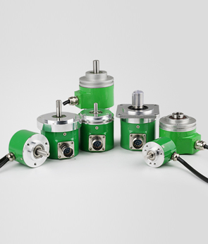
Incremental encoder
Each turn a unit, the encoder outputs a pulse, so called incremental;
Tamagawa incremental encoder output signal has a long-term output, open collector output, voltage output, a complementary push-pull output four ways. Mechanical structure points, then a hollow shaft and the take-up shaft encoder, to meet a variety of different applications.
Tamagawa encoder models, which currently mainly used in elevator traction machine, door machine, servo motor, numerical control equipment and other industries.
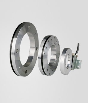
Absolute encoders
Taking a reference point as the origin, the data line is always output of the encoder shaft current positional deviation data origin distance is called absolute encoder. For example, the encoder resolution of a 10-bit BCD code output to 360C / T, then each unit corresponds to 1 °, the axial misalignment of origin if a unit is in 1 ° position, then the output 0000000001 Any deviation from 50 °, which is in 50 ° position, then the output is 0001010000. Absolute encoders always outputs current position information. Due to such characteristics, the absolute encoder is ideal for applications running track occasions.
Tamagawa absolute encoder model is complete, from the encoding of the output signal to the classification, then there BCD code, GRAY code and pure binary code (PB) output; from the output mode to divide words parallel output and serial output; from resolved rate to divide, then there ranged from 8-36. The user can choose according to their needs.
Moreover absolute encoder as well as single-turn and multi-turn points, multi-turn count the number of turns and a single rotary excluding laps, Tamagawa absolute encoder single rotation can be done up to 20, 16-bit multi-turn. Serial transmission output signal, after conversion into a dedicated chip parallel output signal can be directly sent to DSP, MCU, FPGA and other processing.
Output circuit interface
For the resolution is not very high in terms of the absolute encoder, generally suitable for parallel output, this interface circuit is simple, and the communication rate is high. Parallel output encoder output circuits are mainly open collector (Figure 1) and the emitter follower (shown in Figure 2) in two ways. Open collector output mode clients need to add pull-up resistor, as shown in dashed lines in FIG. 1; emitter-follower mode, pull-down resistor should be added,
As shown in phantom in FIG.
Corresponding to the output data line from 1,2,22 ... 2? Bits of data, the user can simply read the encoder data directly from the data bus.
 Previous:Rotary encoder and resolver Next:Cable displacement sensor working principle
 Products